Controlling an LED via GPIO
The goal of this guide is to connect an LED to the Raspberry Pi GPIO's and turn it on and off. Next the LED class build earlier needs to be adapted to make use of the GPIO and control a real life LED.
Introduction
The Raspberry Pi has several GPIO (General Purpose Input Output) pins that can be used to connect all kinds of hardware. Using a little software you change their state to be HIGH (1) or LOW (0) or you can read the value that external hardware is presenting at the input.
This hands on will guide you through the process of attaching an LED to a GPIO of the Raspberry Pi and controlling it via a small Python script.
In addition to your Raspberry Pi running Raspbian, you will also need:
- A Breadboard
- An LED
- A 1k resistor
- Two male-female jumper wires
Most of this can be found in the Arduino Starter Kit provided. The jumper wires can be found in a separate box provided by the lector.
The LED has an anode and a cathode side. The anode side should be connected to the positive supply, while the cathode should be connected to the ground.
A diagram to identify both sides is shown below:
![Cathode and Anode of an LED[^1]](img/ledwiring.jpg)
1. Source http://www.blocksignalling.co.uk/index.php/traffic-lights-module-common-anode-tlc2a ↩
If we were to connect the LED directly to the power supply it would draw way to much current and blow up. To limit the current we need to place a resistor in series with the LED (as shown in the schematic in the next section). For this a 1k resistor can be used.
![A 1k resistor[^2]](img/1k_resistor.jpg)
2. Source https://www.pinterest.com/pin/794040978023017042/?autologin=true ↩
While a 1k resistor works to limit the current through the LED, it will not be ideal for the voltage and type of LEDs used here. In practice you should always take the voltage drop of the LED, the power supply and the preferred current (often 10mA or 20mA) into account. There are various sites you can use for this like for example: http://www.ohmslawcalculator.com/led-resistor-calculator.
Hardware Schematic and BreadBoard
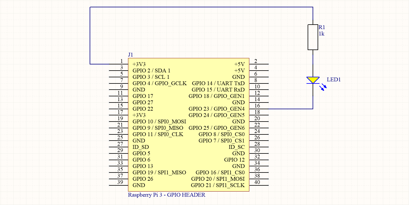
It is important not to make the GPIO provide to much power as these are directly connected to the processor pins and no protection for overcurrent is provided. A microcontroller / microprocessor is not able to provide much current.
By connecting the anode side of the LED to VCC (+3V3 in this case) via a resistor, we actually do not let the GPIO source the current. The current is sourced by the power supply and it is sinked via the GPIO. A GPIO is often able to sink much more current than it can source.
Deciding what GPIO pin to use is not always easy. You need to make sure you are connecting to an already used pin or to a pin with a special function. A website such as https://pinout.xyz/ can be a nice aid.
Available GPIO pins are: GPIO18, GPIO23, GPIO24, GPIO25, GPIO12, GPIO16, GPIO17, GPIO27, GPIO22, GPIO5, GPIO6, GPIO26.
Here we make use of GPIO23 to connect the cathode of the LED.
Connecting everything correctly should show a similar result to the image shown below.
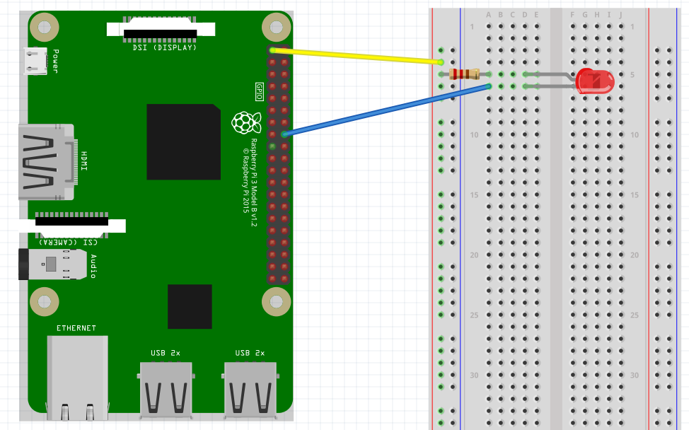
Info: Fritzing
The above image was created using a tool called Fritzing. Fritzing is an open-source hardware initiative that makes electronics accessible as a creative material for anyone. They offer a software tool, a community website and services in the spirit of Processing and Arduino, fostering a creative ecosystem that allows users to document their prototypes, share them with others, teach electronics in a classroom, and layout and manufacture professional PCBs.
Example program
A small example program that turns the LED on and back off after 1 second is shown below:
import wiringpi
from time import sleep

wiringpi.wiringPiSetupGpio()    # Use GPIO numbering

PIN_NUMBER = 23    # Use GPIO23 for the LED

wiringpi.pinMode(PIN_NUMBER, 1)        # Set LED pin to 1 ( OUTPUT )

print("Setting LED on")
wiringpi.digitalWrite(PIN_NUMBER, 0)   # Write 0 ( LOW ) to LED pin

sleep(1)

print("Setting LED off")
wiringpi.digitalWrite(PIN_NUMBER, 1)   # Write 1 ( HIGH ) to LED pin

print("Done")
Save this program in a python file called for example led_hw.py. Execute it to verify that your hardware is working properly.
Guide
Let us extend the Led class from the previous hands on and add the hardware interaction to it.
Below is the code to start from (this is the solution of the Led class placed below the imports of the previous code example):
import wiringpi
from time import sleep

class Led(object):
  def __init__(self):
    self.off()

  def on(self):
    self.set_state(True)

  def off(self):
    self.set_state(False)

  def set_state(self, state):
    self.isOn = state

  def get_state(self):
    return self.isOn

# The main program
wiringpi.wiringPiSetupGpio()    # Use GPIO numbering

PIN_NUMBER = 23    # Use GPIO23 for the LED

wiringpi.pinMode(PIN_NUMBER, 1)        # Set LED pin to 1 ( OUTPUT )

print("Setting LED on")
wiringpi.digitalWrite(PIN_NUMBER, 0)   # Write 0 ( LOW ) to LED pin
sleep(1)

print("Setting LED off")
wiringpi.digitalWrite(PIN_NUMBER, 1)   # Write 1 ( HIGH ) to LED pin

print("Done")
First of all we can place the initialization of the wiringPi GPIO library in the constructor of our Led class. This will automatically take care of the initialization when an Led object is created. You can remove the line of code from your main program code.
# .....
class Led(object):
  def __init__(self):
    wiringpi.wiringPiSetupGpio()    # Use GPIO numbering
    self.off()
# .....
Next we create an attribute pinNumber that holds the number of the GPIO pin. It can be initialized to the value of 23 inside the constructor of our Led class as shown below:
# .....
class Led(object):
  def __init__(self):
    self.pinNumber = 23
    wiringpi.wiringPiSetupGpio()    # Use GPIO numbering
    self.off()
# .....
Last we should also set the pinmode of the GPIO inside the constructor. We place it here because it should only be set once for an Led and it should be set before we change the actual value of the GPIO. Do make sure to place it behind the initialization of the wiringPi library (same as in the main program). The PIN_NUMBER does need to be replaced by self.pinNumber, the attribute we initialized earlier.
# .....
class Led(object):
  def __init__(self):
    self.pinNumber = 23
    wiringpi.wiringPiSetupGpio()    # Use GPIO numbering
    wiringpi.pinMode(self.pinNumber, 1)        # Set LED pin to 1 ( OUTPUT )
    self.off()
# .....
Summarized, the constructor of the Led class creates an attribute with the pin number of the GPIO we want to use for the Led. It initializes the wiringPi library and it sets the GPIO as an output. Last it also turns the Led off.
The last part of the Led class we need to modify is the set_state method to actually set the GPIO based on the value of the state. This can be achieved by calling the digitalWrite() method of wiringPi with self.pinNumber and state as arguments.
# .....
class Led(object):
  # .....
  def set_state(self, state):
    self.isOn = state
    wiringpi.digitalWrite(self.pinNumber, state)   # Write 0 ( LOW ) to LED pin
# .....
All the code that was placed inside the Led class can now be removed from the main program. Instead we need to create an Led object and call the on() and off() methods.
import wiringpi
from time import sleep

# ....

# The main program
led = Led()

print("Setting LED on")
led.on()

sleep(1)

print("Setting LED off")
led.off()

print("Done")
Our main application is a lot cleaner and more readable now.
Challenge
Now try for yourself to alter the main program to let the LED flash a number of times using a loop.
The full solution can be found in the solutions section.